Busbar, terminals, links and devices map to defined circuits.
CP electrical assemblies
Cathodic Protection Junction and Bonding Boxes
Cathodic protection junction and bonding boxes collect, distribute, bond or monitor low-voltage DC circuits. Their reliability depends on correct current paths, component ratings, cable interfaces, environmental protection and unambiguous identification.
CathPro supplies anode junction, negative distribution, bonding and monitoring boxes to the agreed general arrangement, schematic and component schedule.
Send the GA, schematic or component schedule directly. No form required. Email: sales@cathprocp.com
Configured to your drawing and component scheduleStandards mapped by scopeData fields stated explicitly
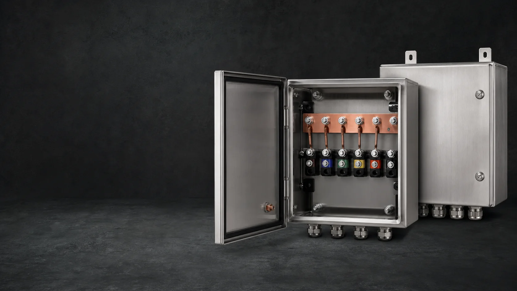
Glands, bend space, mounting and environmental protection align.
Component values, polarity, labels and continuity are checked.
Product overview
Specify your CP junction or bonding box
Send the box function, terminal count, cable sizes and entries, required links or shunts, enclosure material and protection requirements. Include your schematic or general arrangement, quantity and delivery destination so the quotation can cover the required configuration.
- Primary functions
- Collect anode leads, distribute negative circuits, create controlled bonds and provide measurement access.
- Typical enclosures
- Stainless steel, painted carbon steel, GRP or other project-selected industrial enclosure.
- Critical interfaces
- Busbar current capacity, terminal conductor range, shunt/link values, gland OD range and circuit identification.
- Configuration control
- The GA, schematic, cable schedule and BOM must agree before assembly begins.
Product construction
What the finished product contains
A good box is laid out around real conductor sizes and field work. Component spacing must allow cable routing, tightening, testing and later maintenance without hiding circuit identity.
Enclosure and mounting
Material, dimensions, door/cover, lock, backplate, wall/pole/floor mounting and environmental protection selected for the site.
Busbar system
Copper or tinned-copper bar with section, support spacing, current rating, drilling and touch protection defined on the drawing.
Terminals
Stud, bolt or industrial terminal blocks sized for the conductor, lugs and expected current, with usable tightening clearance.
Links and measuring components
Removable links, calibrated shunts, resistors, diodes or decoupler interfaces installed only when shown on the schematic.
Cable entries
Glands, earth studs, spare plugs and internal bend space coordinated to the cable schedule.
Circuit identification
External box tag, terminal IDs, polarity, circuit function and warning labels linked to the approved schematic.
Premium product studies
Products, configurations and critical interfaces
Premium studio product studies show representative open, closed and compact CP enclosures. They clarify layout and cable-entry options; environmental ratings and component compliance require the specified evidence for the selected assembly.
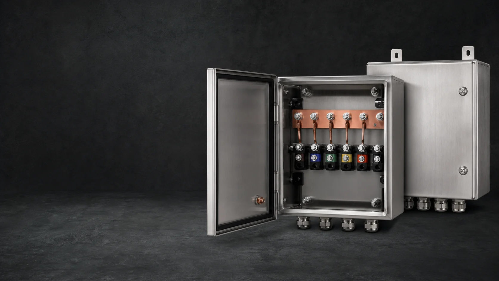
Busbar, terminals and gland entries organized to the schematic
Current rating, terminal spacing, conductor sizes and enclosure clearances are checked as one configured assembly.
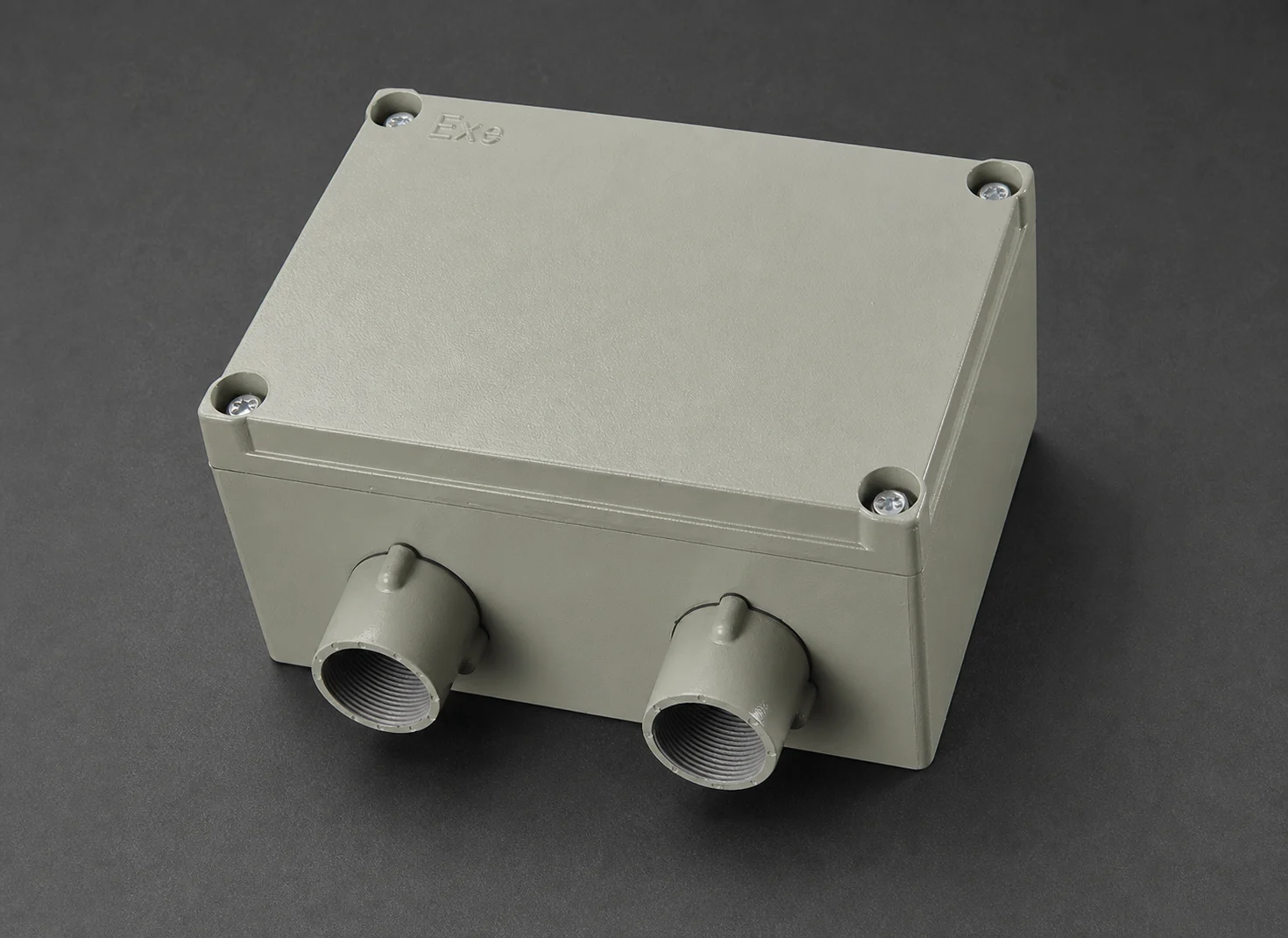
Housing size selected around the internal component
Entry count, thread, gland range and sealing arrangement follow the cable schedule and environmental requirement.
Material and access adapted to the service location
Stainless, coated steel or nonmetallic options are stated with the required IP, IK or NEMA evidence boundary.
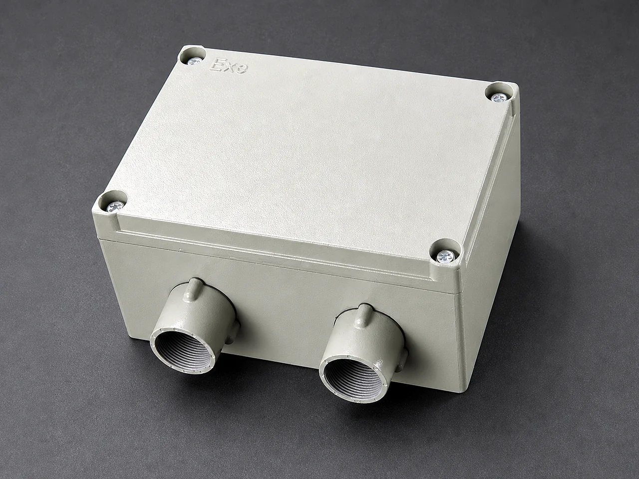
Cable interfaces specified before assembly
Threads, glands, conductor range, strain relief and spare-entry sealing are reconciled against the approved schedule.
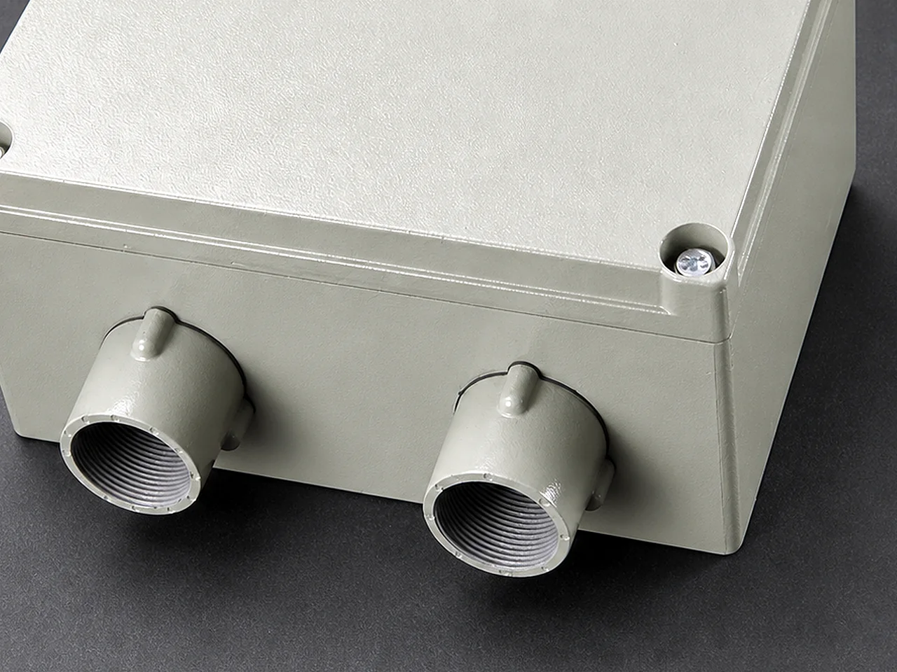
Entry thread and sealing face remain inspectable
The selected gland must match thread form, cable outside diameter, armor and environmental sealing requirements.
Product families
Configurations covered by this product range
Each configuration is released against its own datasheet, drawing or component schedule. Similar appearance does not make the technical definitions interchangeable.
Anode junction box
Collects individual galvanic or impressed-current anode leads onto busbars, links or monitored shunts.
Negative distribution box
Distributes transformer-rectifier negative circuits to structure cables under a controlled schematic.
Bonding box
Provides removable links, shunts, resistors or diodes for intentional bonds and current measurement.
Monitoring/interface box
Provides accessible terminals and defined space/interfaces for approved measurement or monitoring equipment.
Applicable standards
Standards mapped to the part they actually control
Listing a standard is not a certification claim. The purchase specification must identify the required edition, clauses, tests and evidence. Project documents take precedence where they add or modify requirements.
| Standard and role | Scope | How it applies to this product |
|---|---|---|
| ISO 15589-1:2026CP system standard | Cathodic protection of on-land pipeline transportation systems, covering design, materials, equipment, installation and inspection. | The system designer's requirements for anodes, monitoring points, cabling, equipment and commissioning. It is not a standalone manufacturing certificate for every component. |
| NACE SP0169-2024Corrosion-control practice | Control of external corrosion on underground or submerged metallic piping systems. | CP criteria, design and installation context. Product configuration still follows the purchase specification and approved drawings. |
| IEC 60529:1989+A1:1999+A2:2013Enclosure classification | IP Code classification for protection provided by electrical enclosures. | A required IP rating must be stated and supported by the selected enclosure or agreed assembly verification; it cannot be inferred from appearance. |
| IEC 62262:2002+A1:2021Mechanical-impact classification | IK Code classification for protection of electrical enclosures against external mechanical impacts. | Apply only when an IK rating is specified and supported by the enclosure design or evidence included in the order scope. |
| IEC 61666:2010+A1:2021Terminal identification | General principles for identification of terminals within industrial systems and equipment. | Terminal designations and schedules where the project adopts this identification approach. |
| ANSI/NEMA 250-2020Enclosure classification | Classification and description of enclosures for electrical equipment rated up to 1,000 V. | Use when the project specifies a NEMA Type. A type claim requires suitable enclosure construction and the applicable verification basis. |
Edition review completed 22 July 2026. The edition named in the project requisition or purchase order remains the contractual basis.
Technical Data Sheet
Parameters buyers and engineers can verify
Numeric values are shown only where a current CathPro datasheet or recognized reference supports them. Custom assemblies use explicit project-defined fields instead of invented catalogue values.
Enclosure datasheet
Environmental suitability is specified, not guessed from material or appearance.
| Parameter | Required definition | Evidence/inspection |
|---|---|---|
| Material | Stainless grade, carbon steel/coating, GRP or project material | BOM/material record |
| Dimensions | External envelope, backplate and usable internal clearances | Approved GA and dimensional report |
| Protection | IP Code or NEMA Type; IK rating where required | Enclosure evidence or agreed assembly verification |
| Access | Door/cover, hinge, lock, gasket and opening direction | Functional and visual check |
| Mounting | Wall, pole, frame, floor or project bracket | GA and fit-up check |
| Earth/bonding | Earth stud, door bond and enclosure bonding arrangement | Continuity check where applicable |
Electrical assembly datasheet
Ratings and dimensions are fixed from the electrical design and cable schedule.
| Assembly item | Controlled data | Factory record |
|---|---|---|
| Busbar | Material/plating, section, hole pattern, current rating and supports | BOM, dimensions and continuity |
| Terminals | Type, conductor range, stud size, current rating, count and spacing | BOM and terminal schedule |
| Links | Material, section, hole centers and removable hardware | Dimensional/component check |
| Shunts | Rated current, mV drop, resistance, tolerance and polarity marking | Certificate/value verification when specified |
| Resistors/diodes | Electrical rating, tolerance, polarity, thermal and mounting requirements | Manufacturer data and point-to-point check |
| Internal wiring | Conductor size, insulation, color, route and terminations | Wiring schedule and continuity |
Cable and gland schedule
Cable OD and lug geometry are needed before enclosure drilling and component spacing are finalized.
| Cable ID | Datasheet fields | Design impact |
|---|---|---|
| Incoming/outgoing circuits | Function, conductor size, insulation OD and quantity | Terminal/lug and busbar sizing |
| Entry | Top/bottom/side, gland thread and gland material | Enclosure drilling and water path |
| Termination | Lug material, palm hole, barrel and insulation support | Terminal stud and working clearance |
| Spare entries | Quantity, size, blanking plugs and future cable range | GA and environmental protection |
| Identification | Cable tag, terminal ID and polarity | Marking schedule and FAT |
Supply and assembly control
From approved data to an inspectable product
The supplied assemblies follow released drawings, controlled interfaces and inspection records. No unapproved change is treated as equivalent by default.
Document coordination
Cross-check the GA, schematic, cable/gland schedule, terminal schedule and BOM before release.
Enclosure preparation
Drill or machine entries and mounting features without compromising the specified enclosure system.
Busbar specification and preparation
Confirm the busbar section, hole pattern, finish and support arrangement against the approved specification.
Component mounting
Install terminals, links, shunts, devices, glands and earth hardware with required spacing and access.
Internal connections
Wire or link circuits to the approved schematic using identified conductors and controlled terminations.
Marking and FAT
Apply tags, then verify components, values, polarity, continuity, point-to-point wiring and enclosure condition.
Packing
Protect doors, glands, loose links/keys and internal components; include item-specific drawings and packing identification.
Inspection and test plan
Checks tied to a stated acceptance basis
Inspection is useful only when the method, acceptance document and product identity are recorded together.
| Inspection item | Method or record | Acceptance basis |
|---|---|---|
| GA compliance | Dimensions, material, entries, mounting and access | Approved general arrangement |
| BOM compliance | Busbar, terminals, links, shunts, devices and glands | Approved bill of materials |
| Point-to-point wiring | Continuity, polarity and circuit mapping | Approved schematic and terminal schedule |
| Component values | Shunt/resistor/diode ratings and certificates where required | Project datasheet/ITP |
| Labels and enclosure | External/internal tags, finish, gasket and protection evidence | Marking and environmental requirements |
Application range
Where this product family is used
- Groundbed anode collection
- Transformer-rectifier distribution
- Pipeline bonding points
- Interference mitigation bonds
- Tank CP distribution
- Monitoring locations
- Plant CP systems
- Maintenance replacement assemblies
Engineering selection notes
Points that should remain visible in technical review
- Terminal count alone cannot size an enclosure; cable bend radius, lug access, busbar spacing and device heat/clearance also matter.
- IP and NEMA systems are not identical, and neither rating should be claimed without the required design and evidence.
- For hazardous locations, provide area classification and certification requirements before any enclosure or component is selected.
Documentation
Evidence that follows the supplied item
The final document set is defined by the order and ITP. Availability depends on the product, inspection scope and approved vendor-data requirements.
General arrangement
Enclosure, layout, cable entries, mounting and overall dimensions.
Schematic and terminal schedule
Circuit functions, links, devices, terminal IDs and polarity.
Component datasheets
Ratings and manufacturer data for terminals, shunts, resistors, diodes, glands and enclosures.
FAT report
Dimensional, BOM, point-to-point, continuity, value and labeling checks.
As-built document set
Final drawing revision and approved deviations reflected after final assembly.
Technical questions
Common specification points
Answers focus on product definition and evidence, not on sales instructions.
What documents prevent box-layout errors?
The general arrangement, schematic, terminal schedule, cable/gland schedule and BOM should use the same circuit IDs and drawing revision.
How are shunts specified?
State rated current, millivolt drop or resistance, tolerance, terminal geometry, polarity/marking and whether a calibration certificate is required.
Can a standard enclosure be drilled without affecting its rating?
Cable entries, glands, plugs and modifications must be compatible with the selected enclosure system. The required rating and evidence scope should be reviewed after the complete assembly is defined.
What is checked during FAT?
Typical checks cover dimensions, BOM, terminal and gland schedules, point-to-point continuity, component values/polarity, labels, access, finish and documentation.