Different housings, maintenance needs and connection arrangements.
Cathodic protection monitoring
Cu/CuSO4 Reference Electrodes
A Cu/CuSO4 reference electrode is the stable half-cell used to measure structure-to-electrolyte potential in soil and other compatible environments. Reliable readings depend on the copper element, saturated electrolyte, porous junction, housing, cable and measurement procedure operating as one system.
CathPro supplies portable field electrodes and permanent buried configurations. The product datasheet must distinguish construction and verification requirements from the CP criterion or survey method used by the corrosion engineer.
Send the quantity, application, cable and specification directly. No form required. Email: sales@cathprocp.com
Supply identity: Project-sourced from qualified manufacturers; supplied and documented by CathProStandards mapped by scopeData fields stated explicitly
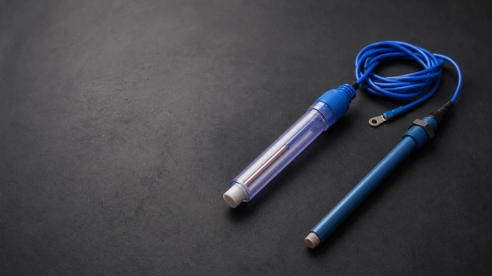
Electrolyte condition and porous junction are critical.
Acceptance band and temperature are stated in the datasheet.
Product overview
The technical definition comes before the catalogue name.
A controlled product page separates the component's function, product construction and acceptance data from the wider cathodic protection design. This prevents a familiar name from hiding missing material, interface or inspection requirements.
- Primary function
- Provide a reproducible reference potential for pipe-to-soil and other structure-to-electrolyte measurements.
- Typical services
- Routine surveys, close-interval work, test stations, tank monitoring and permanent CP monitoring points.
- Critical interfaces
- Porous junction contact with the electrolyte, cable continuity, connector compatibility and temperature-aware verification.
- Standard position
- There is no single universal product-construction standard; the approved electrode datasheet defines the supplied item.
Product construction
What the finished product contains
The electrode is an electrochemical assembly. Housing appearance alone does not demonstrate stability, junction condition or measurement suitability.
Copper element
Clean, stable copper element with material, surface preparation, immersed length and electrical connection defined by the product design.
Copper sulfate electrolyte
Saturated CuSO4 solution maintained with excess crystals where the design requires visible saturation reserve.
Porous junction
Ceramic or project-selected porous interface that provides ionic contact while retaining electrolyte and limiting contamination.
Housing
Refillable portable body or sealed permanent body selected for field handling, burial and the expected maintenance strategy.
Cable and termination
Specified conductor, insulation, lead length, strain relief, polarity identification and meter/test-station termination.
Protective and service accessories
Tip protection, storage cap, filling/vent features or installation protection according to the electrode type.
Premium product studies
Products, configurations and critical interfaces
Premium product studies present representative portable and permanent reference-electrode forms, cable interfaces and sensing ends. Model-specific potential verification and construction remain controlled by the datasheet and inspection record.
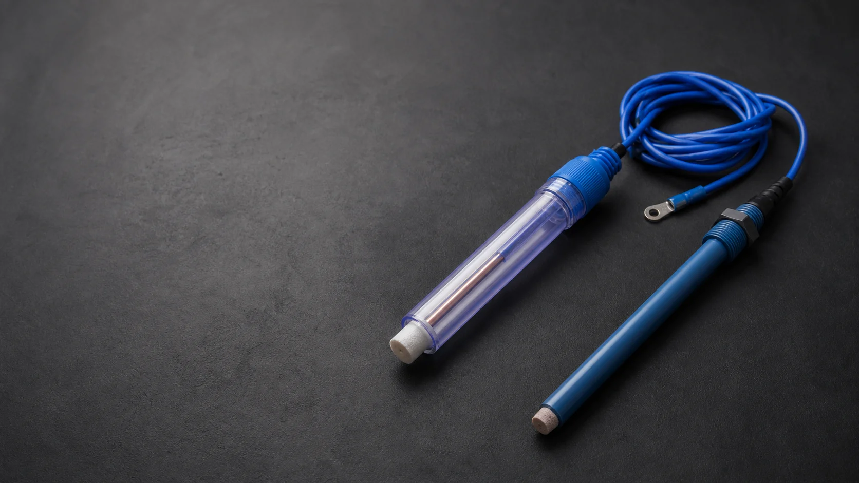
Portable and permanent assemblies shown together
Reference chemistry, housing, porous interface, cable and connector are defined for each model and service environment.
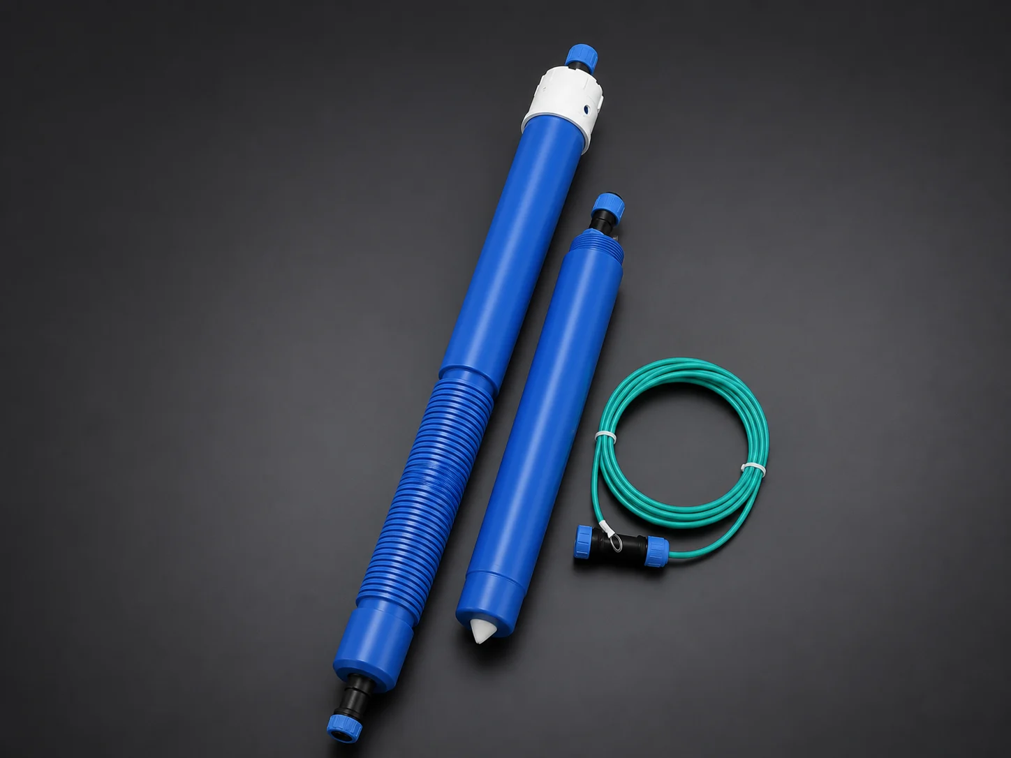
Mechanical protection matched to installation
Housing length, sensing interface and cable exit are selected for the soil, access and protection requirements.
Reference chemistry remains explicit
Cu/CuSO4, Ag/AgCl and zinc references are not interchangeable; every value is stated against its reference scale.
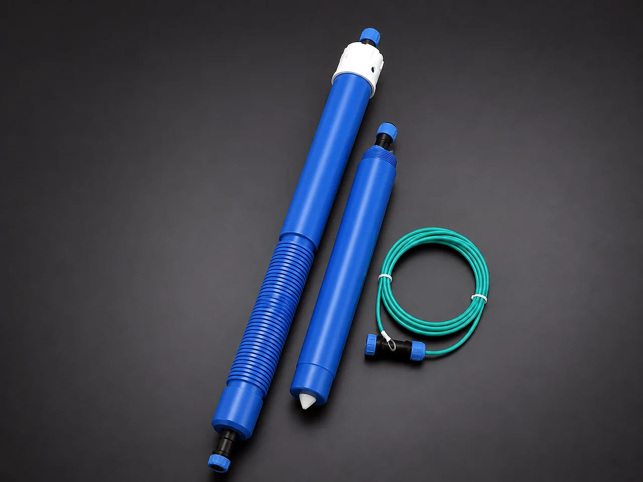
Cable, connector and sensing body kept identifiable
Electrical continuity and potential comparison are recorded under the agreed conditioning and test procedure.
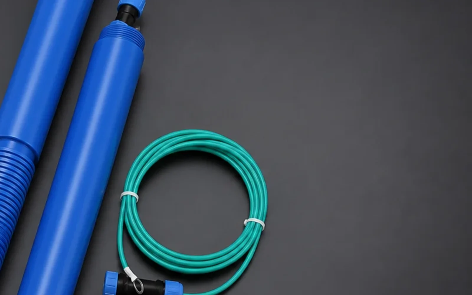
Body, threaded section and lead shown at inspection scale
Construction details are confirmed against the model drawing and potential-verification procedure rather than color alone.
Product families
Configurations covered by this product range
Each configuration is released against its own datasheet, drawing or component schedule. Similar appearance does not make the technical definitions interchangeable.
Portable refillable electrode
Field-survey unit with inspectable electrolyte and junction, protective cap and meter-compatible lead.
Portable sealed electrode
Compact field unit intended for routine measurements without user electrolyte replenishment.
Permanent buried electrode
Long-term installation with sealed housing, fixed cable lead and mechanical protection for the junction and cable exit.
Test-station integrated electrode
Permanent electrode supplied with cable length and termination coordinated to the terminal schedule.
Applicable standards
Standards mapped to the part they actually control
Listing a standard is not a certification claim. The purchase specification must identify the required edition, clauses, tests and evidence. Project documents take precedence where they add or modify requirements.
| Standard and role | Scope | How it applies to this product |
|---|---|---|
| NACE TM0497-2022Measurement method | Field measurement techniques related to CP criteria on underground or submerged metallic piping. | Measurement arrangement, reference-electrode use and cautionary measures. It does not define a universal reference-electrode product construction. |
| ISO 15589-1:2026CP system standard | Cathodic protection of on-land pipeline transportation systems, covering design, materials, equipment, installation and inspection. | The system designer's requirements for anodes, monitoring points, cabling, equipment and commissioning. It is not a standalone manufacturing certificate for every component. |
| NACE SP0169-2024Corrosion-control practice | Control of external corrosion on underground or submerged metallic piping systems. | CP criteria, design and installation context. Product configuration still follows the purchase specification and approved drawings. |
Edition review completed 22 July 2026. The edition named in the project requisition or purchase order remains the contractual basis.
Technical Data Sheet
Parameters buyers and engineers can verify
Numeric values are shown only where a current CathPro datasheet or recognized reference supports them. Custom assemblies use explicit project-defined fields instead of invented catalogue values.
Product construction datasheet
The approved datasheet should define the electrochemical cell and all field interfaces. Values marked project-defined are not replaced by generic assumptions.
| Parameter | Portable configuration | Permanent configuration |
|---|---|---|
| Reference couple | Copper / saturated copper sulfate | Copper / saturated copper sulfate |
| Housing | Refillable or sealed engineering polymer | Sealed burial-rated body by model |
| Porous junction | Replaceable or fixed ceramic junction by model | Protected fixed porous junction |
| Cable | Flexible survey lead and meter connector | Fixed cable type, insulation and project length |
| Maintenance | Electrolyte, crystal and junction condition inspectable | Maintenance strategy and design life defined by model/project |
| Identification | Model, polarity and serial/batch marking | Model, cable length, project tag and batch marking |
Verification and acceptance data
Potential comparison must state the reference, temperature and stabilization procedure. A voltage number without those conditions is incomplete.
| Verification item | Data recorded | Acceptance basis |
|---|---|---|
| Comparison electrode | Master/reference electrode ID and verification status | Approved verification procedure |
| Temperature | Electrode and bath/soil-simulator temperature | Datasheet correction or allowed range |
| Potential difference | Measured mV difference after stabilization | Project- or model-specific acceptance band |
| Polarity and continuity | Cable polarity, continuity and connector assignment | Wiring datasheet |
| Housing/junction condition | Leakage, crystal reserve, junction wetting and physical condition | Product inspection criteria |
| Traceability | Model, serial/batch, cable length and inspection date | Document-control requirement |
A laboratory comparison demonstrates condition at inspection; field accuracy also depends on junction contact, contamination, temperature, instrument impedance and measurement technique.
Installation-interface data
Permanent electrodes need enough interface detail to be installed correctly and later identified at the monitoring point.
| Field | What the datasheet shows | Reason |
|---|---|---|
| Installation environment | Soil, fresh water or other approved service | Confirms compatibility of housing and junction |
| Orientation and depth | Required position and protection arrangement | Maintains electrolyte contact and avoids mechanical damage |
| Cable route | Lead length, conduit/protection and termination | Prevents unplanned splices and misidentification |
| Test-point identity | Terminal designation and polarity | Supports repeatable monitoring |
| Storage/commissioning | Conditioning, cap removal and initial comparison steps | Protects the junction before service |
Technical files
Published product datasheets
Cu/CuSO4 reference electrode datasheetCurrent product summary for portable and permanent reference-electrode supply.Sourcing and verification control
From approved data to an inspectable product
Complete products are project-sourced from qualified manufacturers against the approved model, datasheet and inspection scope. CathPro controls supplier documentation and agreed verification without claiming manufacture.
Requirement review
Confirm service, model, cable, connector and verification requirements before supplier selection.
Qualified-source selection
Select a qualified manufacturer and model whose documented construction matches the approved datasheet.
Supplier-document review
Review the product identity, construction, electrolyte basis, cable and storage data included in the agreed scope.
Incoming inspection
Check model, housing, porous interface, cable, connector, identification and packaging condition.
Agreed verification
Verify lead length, termination, continuity, polarity and potential comparison where included in the ITP.
Document release
Match supplier records and CathPro inspection records to the supplied item and approved requirement.
Export packing
Protect the porous tip and keep storage orientation and conditioning information with the identified unit.
Inspection and test plan
Checks tied to a stated acceptance basis
Inspection is useful only when the method, acceptance document and product identity are recorded together.
| Inspection item | Method or record | Acceptance basis |
|---|---|---|
| Bill-of-material verification | Copper element, housing, junction, electrolyte, cable and connector | Released product specification |
| Housing and seal | Visual/leak condition and assembly completeness | Model inspection criteria |
| Potential comparison | Controlled comparison with master electrode at recorded temperature | Approved acceptance band |
| Electrical continuity | Cable, termination and polarity check | Wiring/product datasheet |
| Identification and protection | Model/batch, lead length, cap and packing condition | Document and packing specification |
Application range
Where this product family is used
- Pipe-to-soil potential surveys
- Close-interval surveys
- Pipeline test stations
- Storage-tank monitoring
- Water-pipeline monitoring
- Buried-structure commissioning
- Fixed monitoring systems
- Maintenance diagnostics
Engineering selection notes
Points that should remain visible in technical review
- Select portable or permanent construction according to how the electrode will be accessed, maintained and replaced.
- State the instrument connector or test-station terminal interface; an otherwise correct electrode can be unusable if the termination is wrong.
- Potential comparison data must include temperature and the reference used, not only a single millivolt value.
Documentation
Evidence that follows the supplied item
The final document set is defined by the order and ITP. Availability depends on the product, inspection scope and approved vendor-data requirements.
Product datasheet
Defines reference couple, construction, housing, junction, cable, storage and intended service.
Verification record
Master-electrode identity, temperature, stabilization and measured difference when included in the order scope.
Installation information
Orientation, junction preparation, cable routing and commissioning precautions for permanent models.
Traceability record
Model, batch/serial, cable length and inspection date.
Technical questions
Common specification points
Answers focus on product definition and evidence, not on sales instructions.
Is there one universal manufacturing standard for Cu/CuSO4 electrodes?
No single standard defines every portable and permanent product construction. The approved datasheet controls the cell, housing, junction, cable and verification, while AMPP and ISO documents govern measurement and system practice.
Why are excess copper sulfate crystals important?
In designs that use them, visible excess crystals help maintain a saturated electrolyte as conditions change. The complete electrolyte and maintenance design remains model-specific.
What should a verification report record?
It should identify the unit and master electrode, temperature, stabilization procedure, potential difference, acceptance band, cable/polarity result and inspection date.
Can portable and permanent electrodes use the same housing?
They may share the same electrochemical couple, but field handling, sealing, porous-junction protection, cable exit and maintenance strategy are different and should be designed accordingly.