Chemistry selected for the intended electrolyte and project basis.
Marine and industrial protection
Cast Zinc Sacrificial Anodes
Cast zinc anodes are drawing-controlled electrochemical components. Alloy chemistry, net anode mass, steel insert geometry, casting soundness and mounting interface must be defined together.
CathPro supports hull, tank, offshore, subsea, cooling-water and special replacement geometries. Product acceptance follows the specified alloy standard, approved drawing and inspection plan rather than catalogue appearance alone.
Technical pageStandards mapped by scopeData fields stated explicitly
Current international reference for cast galvanic anodes in saline service.
Net mass, insert, tolerances and inspection are item-specific.
Product overview
The technical definition comes before the catalogue name.
A controlled product page separates the component's function, product construction and acceptance data from the wider cathodic protection design. This prevents a familiar name from hiding missing material, interface or inspection requirements.
- Primary function
- Provide sacrificial current to more noble metals in seawater, brackish water or other approved electrolytes.
- Typical services
- Ship hulls, ballast tanks, offshore structures, seawater systems, condensers and replacement projects.
- Critical interfaces
- Alloy-to-insert bond, insert welds and dimensions, mounting geometry, net alloy mass and casting quality.
- Design responsibility
- Anode quantity, spacing and life are established by the project CP design, not by the casting supplier alone.
Product construction
What the finished product contains
The visible zinc body is only one part of the item. Insert fabrication and position determine whether the anode can be mounted correctly and transfer current reliably.
Zinc alloy body
ASTM B418 Type I, Type II or project-specific chemistry, cast to the approved profile and controlled net alloy mass.
Steel core or mounting insert
Flat bar, pipe, strap, stud or drawing-specific steelwork with material, weld details and protrusions defined before casting.
Cast-to-insert interface
Insert preparation and mold location controlled to support anchorage, continuity and the specified stand-off or mounting geometry.
Mounting features
Weld-on straps, bolt holes, flush-mount cores, bracelet segments or equipment-specific interfaces made to drawing.
Identification
Heat/batch, item number, drawing revision, individual or pallet marking and traceability method defined in the order.
Premium product studies
Products, configurations and critical interfaces
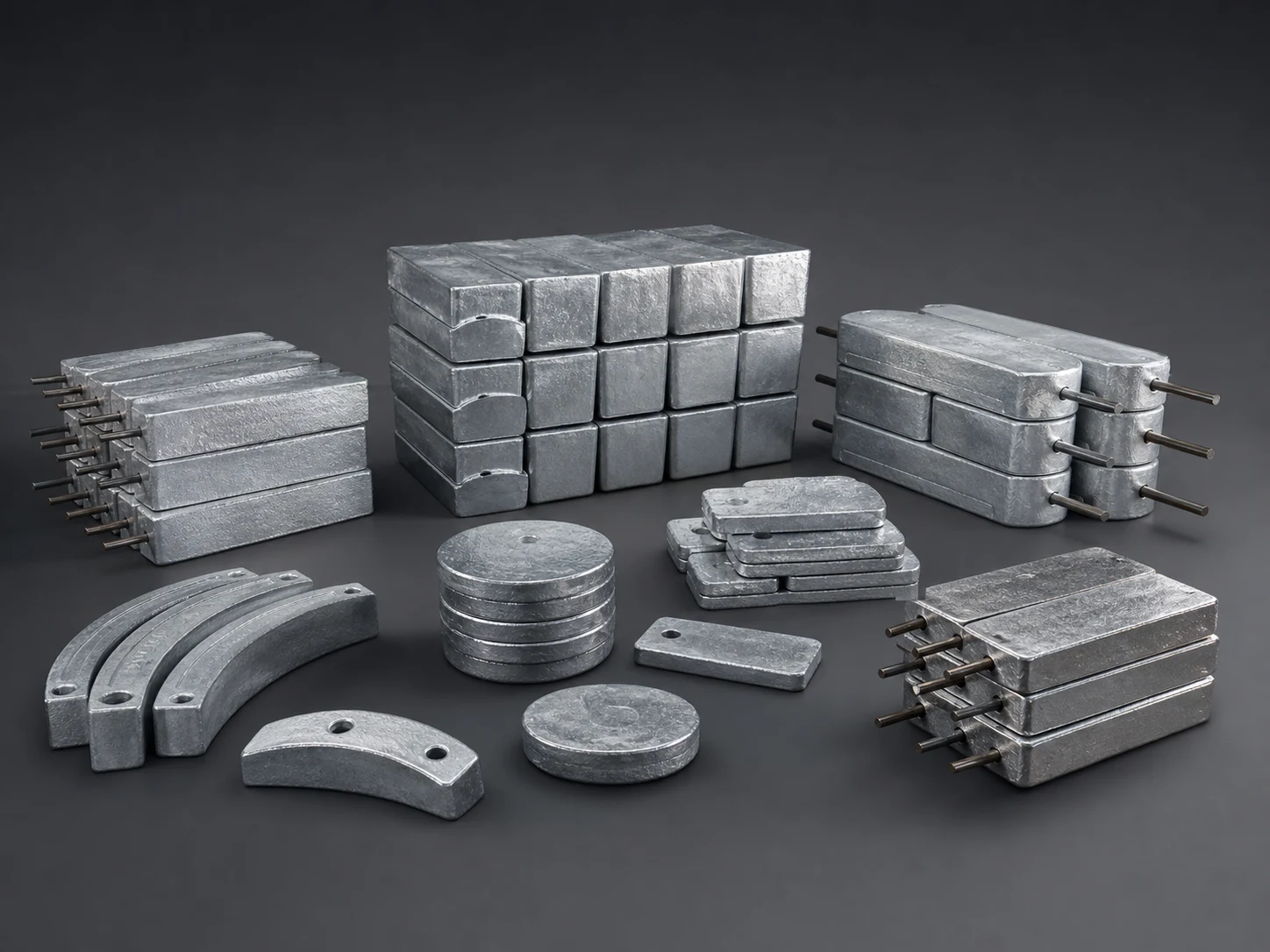
Premium studio product visualizations show representative cast zinc bodies, mounting inserts and bracelet forms without claiming to document a specific production batch. Actual compliance is demonstrated through drawings, reports and traceable release records.
Cast forms organized by geometry and mounting interface
Each item retains its own alloy type, net mass, steel insert, drawing revision and acceptance criteria.
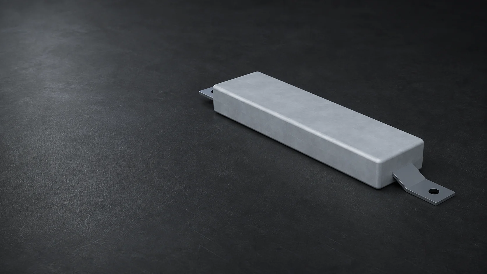
Steel core and alloy body defined together
Insert material, section, projection and cast-to-core interface are verified against the approved drawing.
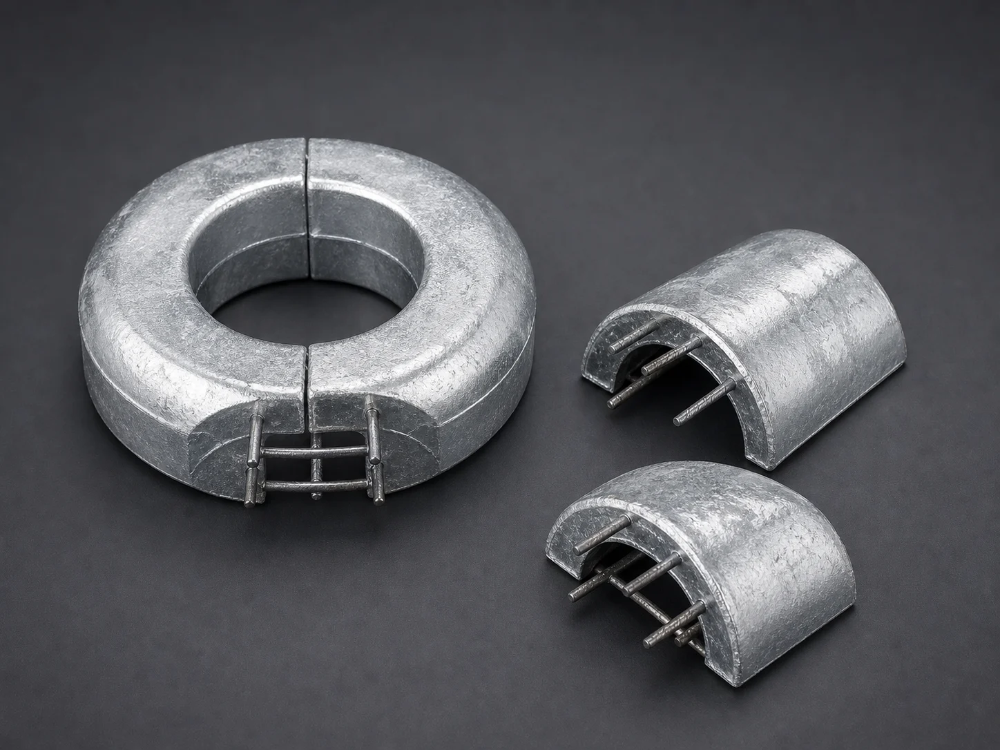
Matched segments controlled for pipe fit-up
Pipe OD, segment angle, gap, core and coating interface remain specific to the offshore-pipeline design.
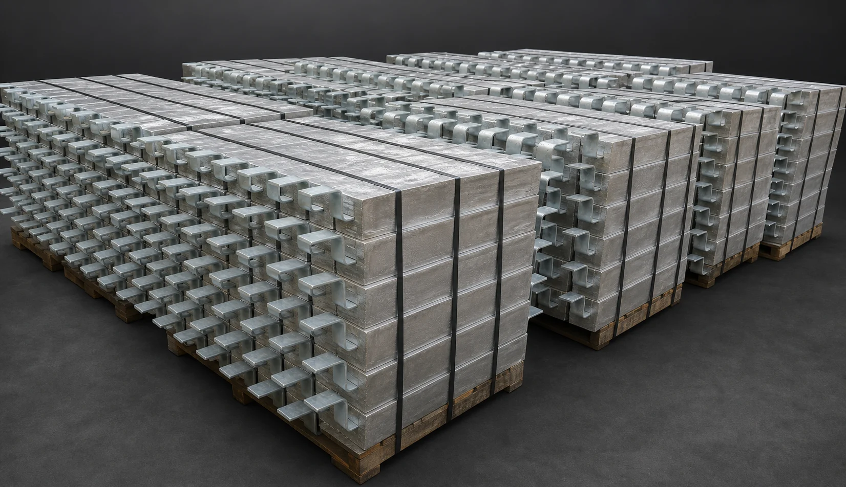
Finished items separated by model and release identity
Packing preserves item, drawing, batch, quantity and package traceability without treating appearance as inspection evidence.
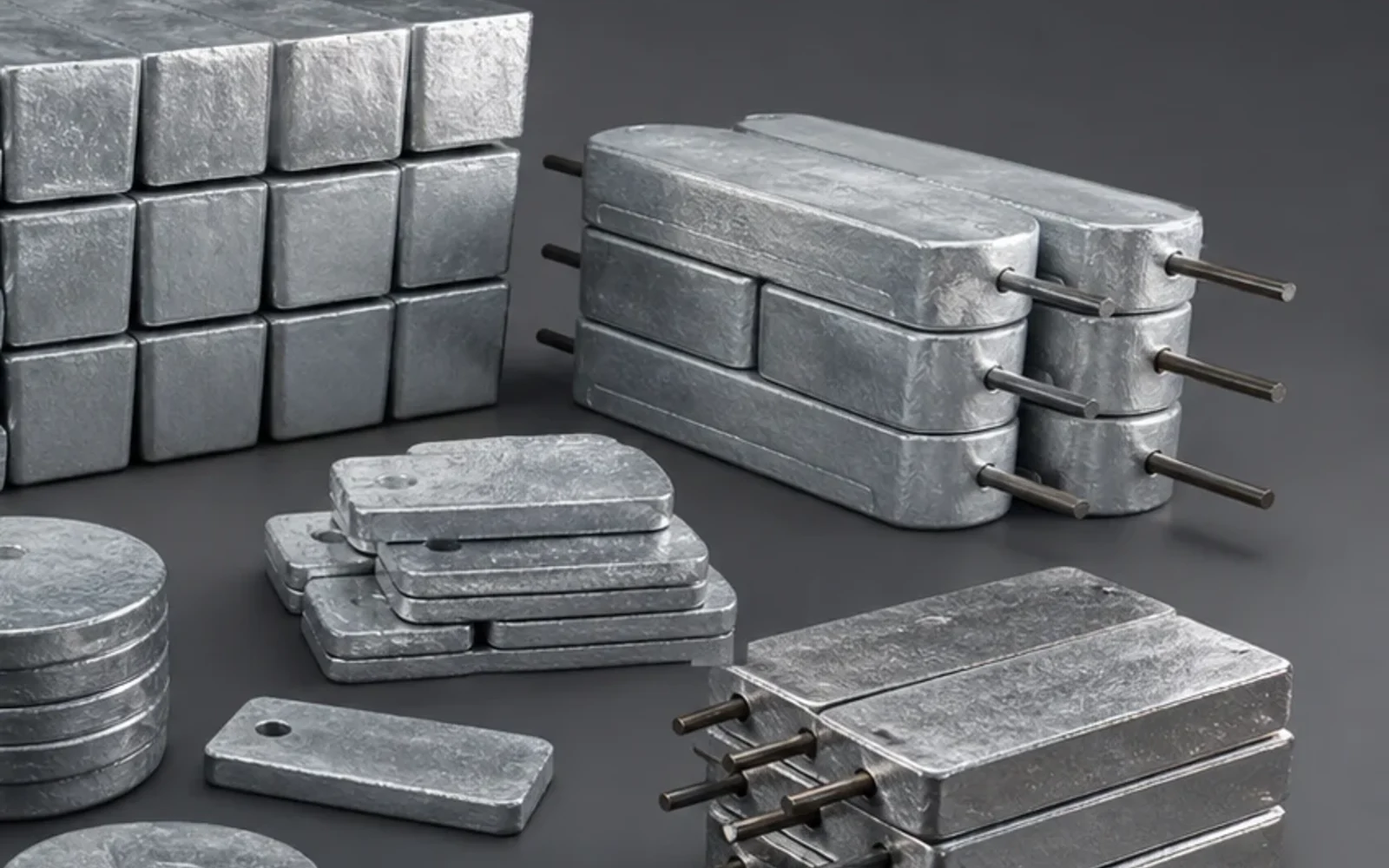
Body form and insert projection reviewed together
A close visual can clarify the interface, but measured dimensions, insert material and net alloy mass remain the acceptance basis.
Product families
Configurations covered by this product range
Each configuration is released against its own datasheet, drawing or component schedule. Similar appearance does not make the technical definitions interchangeable.
Hull and ballast-tank anodes
Flush, stand-off, weld-on and bolt-on forms for immersed steel structures.
Offshore structural anodes
Slender or block castings with project-designed inserts for jackets, frames and subsea equipment.
Bracelet anode segments
Half-shell or segmented geometries for offshore pipelines where the specific pipeline design and SP0492 scope apply.
Cooling-water and equipment anodes
Compact plate, block or cylindrical forms for water boxes, condensers, heat exchangers and OEM assemblies.
Applicable standards
Standards mapped to the part they actually control
Listing a standard is not a certification claim. The purchase specification must identify the required edition, clauses, tests and evidence. Project documents take precedence where they add or modify requirements.
| Standard and role | Scope | How it applies to this product |
|---|---|---|
| ASTM B418-16a(2021)Product specification | Cast and wrought galvanic zinc anodes for seawater, brackish water and other corrosive electrolytes. | Type I or Type II chemistry, sampling and analysis. Geometry, inserts and project inspection remain drawing-controlled. |
| ASTM F1182-07(2023)Marine zinc-anode specification | Common zinc sacrificial-anode shapes for use on ships and small craft. | Use only when the requested marine shape, alloy and installation scope fall within ASTM F1182. Custom castings still require an approved drawing and inspection plan. |
| ISO 9351:2025 / EN ISO 9351:2025Product and inspection standard | Cast aluminum-, magnesium- and zinc-based galvanic anodes for seawater, saline sediment and brackish water. | Chemistry, electrochemical properties, physical tolerances, testing and inspection when this standard is selected by the project. EN ISO 9351:2025 supersedes EN 12496:2013 in Europe. |
| GB/T 4950-2021Chinese product standard | Zinc-alloy sacrificial anodes, including material, product and inspection requirements. | The exact grade, service environment, geometry, insert and project acceptance plan must be stated in the order. |
| DNV-RP-B401 (2021-05)Design and manufacturing practice | Cathodic protection design using aluminum- or zinc-based galvanic anodes, including manufacture and installation guidance. | Project design values, anode manufacture, inspection and installation requirements when DNV-RP-B401 forms part of the design basis. |
| NACE SP0492-2016Specialized product standard | Metallurgical and inspection requirements for offshore-pipeline bracelet anodes. | Use only for bracelet-anode scope. It is not a general standard for hull, tank or every cast zinc-anode geometry. |
Edition review completed 22 July 2026. The edition named in the project requisition or purchase order remains the contractual basis.
Technical Data Sheet
Parameters buyers and engineers can verify
Numeric values are shown only where a current CathPro datasheet or recognized reference supports them. Custom assemblies use explicit project-defined fields instead of invented catalogue values.
Zinc alloy chemistry control summary
ASTM B418 Type I and Type II are distinct alloy families. The standards are referenced by designation and scope without copying their proprietary composition tables.
| Control field | Type I / Type II decision | Acceptance evidence |
|---|---|---|
| Alloy type | State ASTM B418 Type I, Type II, ISO/EN ISO 9351, GB/T 4950 or project chemistry | Approved purchase specification |
| Controlled additions | Aluminum and cadmium requirements differ by selected alloy type | Heat/sample chemical analysis |
| Restricted impurities | Iron, lead, copper and other limits follow the selected standard/grade | Laboratory report tied to batch |
| Base metal | Zinc remainder under the selected composition | Material identity and analysis |
| Sampling | Heat, lot or agreed production-sample frequency | Approved ITP |
Type I and Type II are not interchangeable by default. The active standard edition and order-specific chemistry table govern acceptance.
Casting and insert datasheet
These fields convert the CP design into a manufacturable, inspectable casting.
| Data block | Required definition | Acceptance evidence |
|---|---|---|
| Casting geometry | Drawing revision, overall dimensions, profile, tapers, machining and tolerances | Dimensional report |
| Net alloy mass | Nominal mass and tolerance excluding the steel insert | Calibrated weight record |
| Insert | Material grade, section, length, protrusion, hole pattern and position | Material record and dimensional inspection |
| Insert fabrication | Weld type, WPS or project detail, surface preparation before casting | Fabrication and visual/NDT record if specified |
| Casting acceptance | Surface irregularities, cracks, shrinkage, cold shuts, repair policy | Visual inspection against project criteria |
| Electrochemical tests | Potential, capacity, efficiency, sampling and method when required | Project-defined laboratory report |
Configuration matrix
Zinc anodes are normally produced to approved drawings. The matrix shows the data that changes between common families.
| Family | Typical insert | Mounting data | Key inspection focus |
|---|---|---|---|
| Flush hull | Embedded flat bar or plate | Hull contour, weld lands, stand-off if any | Profile, insert exposure and net mass |
| Stand-off | Bar or pipe core with projecting legs | Leg spacing, projection, weld interface | Insert position and casting support |
| Bolt-on | Studs, plates or drilled insert | Hole centers, thread/fastener interface | Machining, alignment and continuity |
| Bracelet | Segmented steel shell or insert | Pipe OD, gap, segment angle, coating interface | Fit-up, straightness and SP0492 criteria |
| Equipment/OEM | Drawing-specific core | Envelope and mating interface | First-article dimensional report |
Technical files
Published product datasheets
Zinc sacrificial anode datasheetCurrent product summary for cast zinc configurations and project-controlled supply.Manufacturing control
From approved data to an inspectable product
The process is organized around released drawings, material identity, controlled interfaces and inspection records. No unapproved change is treated as equivalent by default.
Drawing and ITP review
Freeze alloy, net mass, insert material, weld details, tolerances, marking and hold points before production.
Insert fabrication
Cut, form and weld the steel core to the controlled drawing, then verify dimensions and specified surface condition.
Mold and insert setup
Locate and secure the insert so protrusions, cover and anode geometry remain within tolerance during casting.
Melt and chemistry control
Prepare the selected zinc alloy, sample by the agreed plan and release the heat against the specified limits.
Casting and controlled cooling
Pour and cool using the approved process, then remove gates and risers without masking relevant surface condition.
Final inspection
Check chemistry, net mass, dimensions, insert position, visible defects, identification and any project-specific tests.
Packing
Support inserts and anode bodies to avoid bending, impact and abrasion, with itemized tags and export packing.
Inspection and test plan
Checks tied to a stated acceptance basis
Inspection is useful only when the method, acceptance document and product identity are recorded together.
| Inspection item | Method or record | Acceptance basis |
|---|---|---|
| Alloy chemistry | Heat/sample analysis for Al, Cd, Fe, Pb, Cu and Zn balance | ASTM B418, ISO 9351 or project chemistry |
| Net alloy mass | Calibrated scale excluding the insert where the drawing defines net mass | Approved drawing tolerance |
| Geometry and insert position | Dimensions, hole centers, protrusions, straightness and fit-up | Approved drawing and ITP |
| Casting surface | Visual examination for cracks, shrinkage, cold shuts, inclusions and unauthorized repairs | Project acceptance criteria |
| Insert fabrication | Material verification, weld visual/NDT and surface preparation when specified | Drawing, WPS and inspection plan |
Application range
Where this product family is used
- Ship hulls
- Ballast and seawater tanks
- Offshore structures
- Subsea equipment
- Marine pipelines
- Condensers and water boxes
- Harbor structures
- Industrial cooling-water systems
Engineering selection notes
Points that should remain visible in technical review
- Specify Type I or Type II from the service environment and project design; the two chemistries are not interchangeable by default.
- A bracelet-anode standard should not be applied uncritically to hull blocks or other unrelated geometries.
- Electrochemical values are meaningful only with a defined test method, reference electrode, temperature and acceptance plan.
Documentation
Evidence that follows the manufactured item
The final document set is defined by the order and ITP. Availability depends on the product, inspection scope and approved vendor-data requirements.
Approved drawing and datasheet
Controls alloy, geometry, net mass, insert, tolerances, marking and tests.
Chemical analysis
Heat or production-sample results linked to the cast items.
Dimensional and weight report
Recorded critical dimensions, insert position and net or gross mass as specified.
Insert fabrication record
Material and weld/NDT records when included in the project inspection scope.
Release and packing record
Visual acceptance, identification, quantity and protected packing arrangement.
Technical questions
Common specification points
Answers focus on product definition and evidence, not on sales instructions.
What does ASTM B418 control?
It covers cast and wrought galvanic zinc anodes and defines Type I and Type II chemical composition requirements. A complete cast-anode order still needs geometry, mass, insert and inspection requirements.
When is ISO 9351 relevant?
ISO 9351:2025 is a current international reference for cast galvanic anodes used in seawater, saline sediment and brackish water. The project must explicitly select its applicable requirements.
What is the most important drawing information?
Net alloy mass, all critical dimensions, insert material and position, weld/mounting interfaces, tolerances, marking and casting-defect acceptance should be unambiguous.
Can one inspection plan cover every zinc-anode shape?
The core controls are similar, but critical dimensions, insert checks, weld records and defect criteria must follow the actual geometry and service.