Coupon design and use are linked to the monitoring objective.
Pipeline monitoring and AC mitigation
Cathodic Protection Polarization Coupons and Probes
Polarization coupons reproduce a defined bare-steel surface connected to the protected structure. When the monitoring arrangement is correctly designed, the coupon supports IR-free potential assessment and measurement of AC or DC current density without treating a conventional structure-to-soil reading as the only evidence.
CathPro supplies project-configured coupons, holders, sealed lead assemblies and test-station interfaces. The CP designer must define coupon material, exposed area, location, connection logic and measurement procedure for the actual pipeline and interference conditions.
Send the coupon area, lead, quantity and test-station specification directly. No form required. Email: sales@cathprocp.com
Supply identity: Project-sourced components; configured and assembled by CathProStandards mapped by scopeData fields stated explicitly
Functions depend on the approved wiring and procedure.
Area, material, seal, leads and tags are stated explicitly.
Product overview
The technical definition comes before the catalogue name.
A controlled product page separates the component's function, product construction and acceptance data from the wider cathodic protection design. This prevents a familiar name from hiding missing material, interface or inspection requirements.
- Primary function
- Provide a defined exposed-steel surface for polarization, potential or current-density monitoring.
- Typical services
- Buried pipelines, AC-interference locations, congested utility corridors, tank-bottom and station monitoring.
- Selection inputs
- Monitoring objective, coupon material, exposed area, soil/electrolyte, AC/DC conditions, reference cell and terminal logic.
- Supply boundary
- Coupon only, coupon with sealed lead, holder/probe assembly, or test-station package according to the approved scope.
Product construction
What the finished product contains
A coupon assembly is useful only when the exposed surface, connection state and measurement interface remain controlled throughout installation and service.
Coupon element
Bare metal selected to represent the monitored structure, with exposed area and geometry stated on the product drawing.
Insulation boundary
Non-exposed surfaces and the coupon/holder interface are sealed so the stated exposed area remains the measurement basis.
Electrical connection
Dedicated copper conductor joined to the coupon by an approved low-resistance method and checked for continuity.
Environmental seal
The metal-to-conductor transition is protected against moisture entry and unintended galvanic contact.
Holder or probe body
Mechanical support and installation interface selected for direct burial, test-station placement or project-specific mounting.
Identification
Coupon function, exposed area, material, cable tag and batch identity are linked to the terminal schedule and product record.
Premium product studies
Products, configurations and critical interfaces
Premium studio product studies explain the coupon/probe, cable, reference and terminal interfaces used at a CP monitoring point. They are product visualizations, while dimensional, continuity and commissioning evidence remains in the approved records.
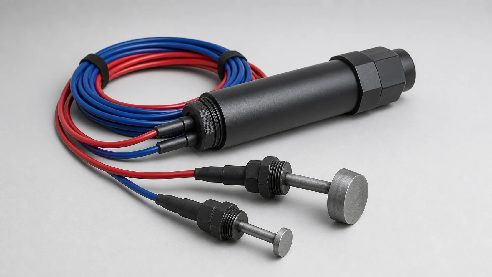
Coupon, holder, leads and terminations controlled together
Exposed area, material, connection state, cable identity and seal are released through the approved drawing and schedule.
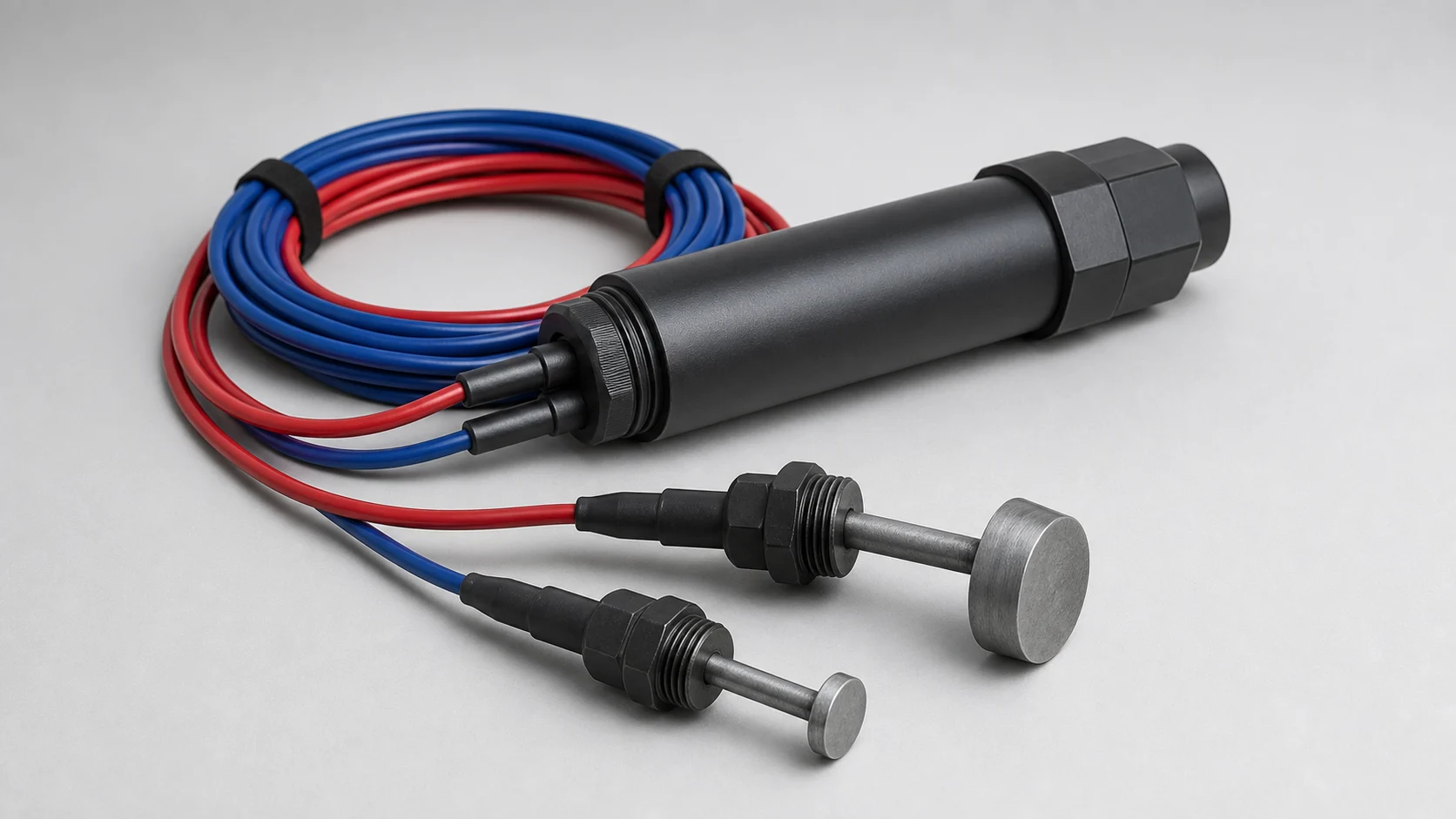
Monitoring geometry selected by the measurement method
The CP designer defines coupon area, orientation, placement and connected or disconnected measurement procedure.
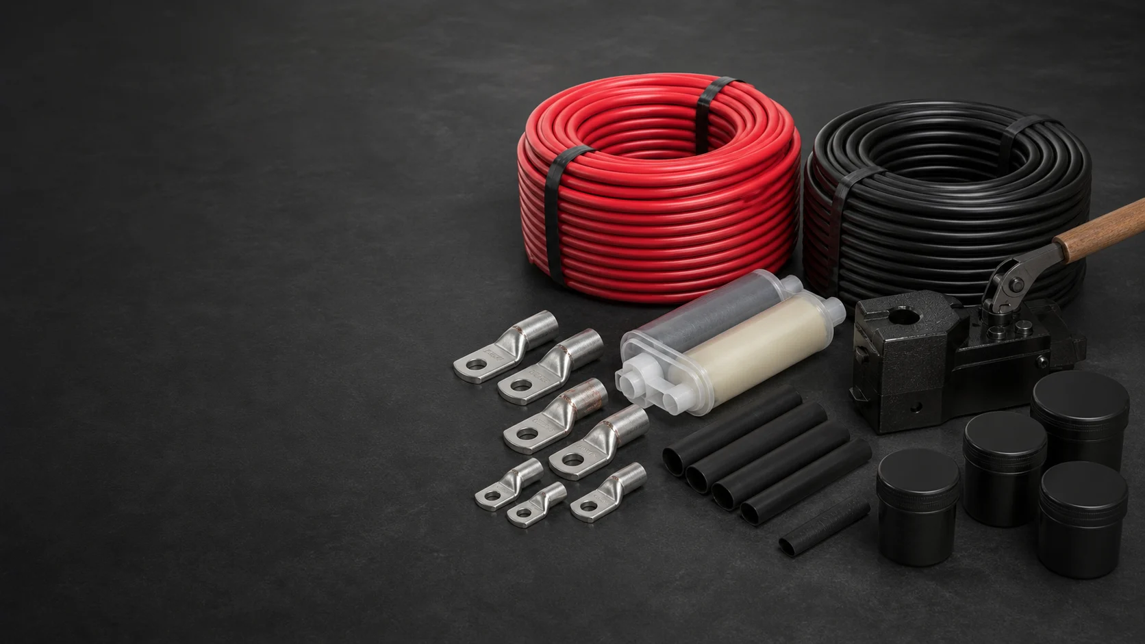
Each lead remains identifiable to the terminal schedule
Conductor, insulation, length, color, tag, joint and termination are checked before the assembly is released.
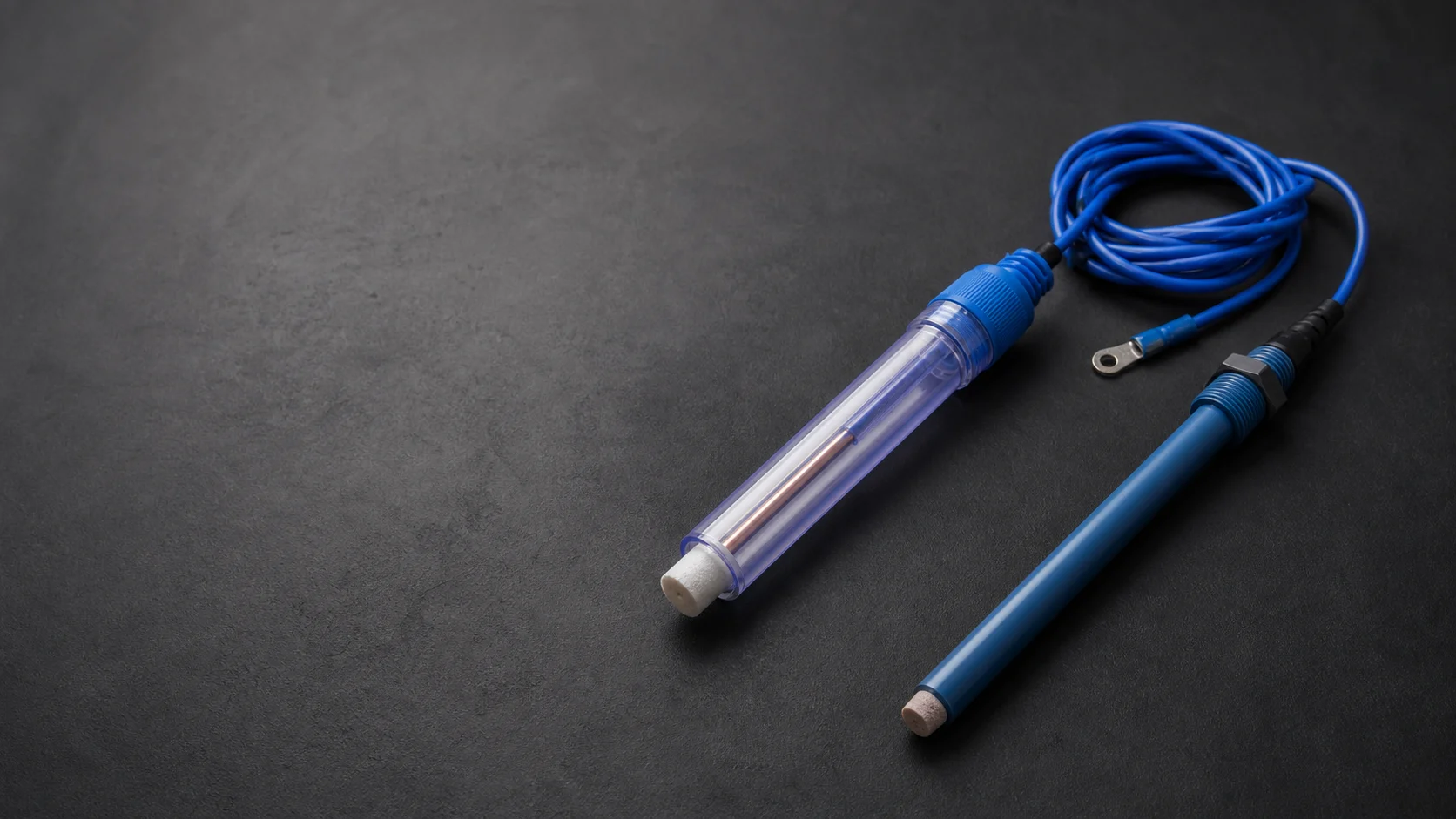
Reference scale and chemistry kept explicit
Coupon measurements are meaningful only when the reference chemistry, temperature and test procedure are stated.
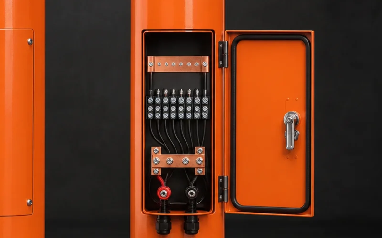
Measurement circuits remain identifiable at the station
Coupon, reference, structure and monitoring leads are reconciled against the terminal schedule before release.
Product families
Configurations covered by this product range
Each configuration is released against its own datasheet, drawing or component schedule. Similar appearance does not make the technical definitions interchangeable.
Polarization coupon
Single defined steel surface for ON/OFF or depolarization measurements under the project procedure.
AC current-density coupon
Defined-area coupon and conductor arrangement for AC current measurement at interference locations.
DC current-density coupon
Separate defined-area circuit for monitoring cathodic-protection current density.
Native coupon
Unconnected or separately controlled element used only where the monitoring design specifies a native comparison.
Integrated probe package
Coupons, reference electrode and connection interface combined under one approved GA and terminal schedule.
Applicable standards
Standards mapped to the part they actually control
Listing a standard is not a certification claim. The purchase specification must identify the required edition, clauses, tests and evidence. Project documents take precedence where they add or modify requirements.
| Standard and role | Scope | How it applies to this product |
|---|---|---|
| ISO 22426:2020Coupon assessment standard | Design, installation, positioning, sizing, use and maintenance of coupons used to assess cathodic-protection effectiveness under normal, AC-interference and DC-interference conditions. | Controls the monitoring method and coupon application. It does not replace the project drawing, cable schedule, exposed-area definition or acceptance inspection for the supplied assembly. |
| ISO 15589-1:2026CP system standard | Cathodic protection of on-land pipeline transportation systems, covering design, materials, equipment, installation and inspection. | The system designer's requirements for anodes, monitoring points, cabling, equipment and commissioning. It is not a standalone manufacturing certificate for every component. |
| NACE SP0169-2024Corrosion-control practice | Control of external corrosion on underground or submerged metallic piping systems. | CP criteria, design and installation context. Product configuration still follows the purchase specification and approved drawings. |
| NACE TM0497-2022Measurement method | Field measurement techniques related to CP criteria on underground or submerged metallic piping. | Measurement arrangement, reference-electrode use and cautionary measures. It does not define a universal reference-electrode product construction. |
Edition review completed 22 July 2026. The edition named in the project requisition or purchase order remains the contractual basis.
Technical Data Sheet
Parameters buyers and engineers can verify
Numeric values are shown only where a current CathPro datasheet or recognized reference supports them. Custom assemblies use explicit project-defined fields instead of invented catalogue values.
Coupon and probe product data
No universal coupon size is assumed. The buyer or CP designer approves the values below for each monitoring location.
| Data field | Required definition | Acceptance evidence |
|---|---|---|
| Coupon material | Metal grade and surface condition representative of the monitored structure | Material record or approved drawing |
| Exposed surface area | Nominal area and tolerance for each AC, DC, polarization or native coupon | Dimensional record and calculation |
| Geometry | Disc, rectangular, cylindrical or project-defined form | Approved drawing |
| Lead cable | Conductor, insulation, color, tag and length | Cable schedule and continuity test |
| Joint and seal | Connection method, strain relief and environmental sealing system | Assembly instruction and visual record |
| Holder/probe | Body material, dimensions, installation interface and burial orientation | GA drawing and final inspection |
Monitoring interface schedule
Product supply and field measurement remain separate scopes, but the interfaces must agree before release.
| Interface | Information to state | Reason |
|---|---|---|
| Structure connection | Cable tag, terminal, normal connection state and disconnect method | Defines coupon polarization condition |
| Reference electrode | Chemistry, cable tag, placement and service environment | Defines the potential measurement basis |
| AC/DC measurement | Coupon area, shunt or analyzer arrangement and units | Supports valid current-density calculation |
| Test station | Terminal schedule, links, labels and enclosure | Keeps measurements repeatable and traceable |
| Installation | Depth, orientation, spacing and backfill/site details | Preserves the monitoring design intent |
Supply and installation handover
The supplied product and the field monitoring method remain aligned through explicit handover data.
| Scope point | Supplier record | Site/engineer confirmation |
|---|---|---|
| Product identity | Coupon function, material, area and serial/tag | Installed location and asset identity |
| Electrical interface | Cable tags, continuity and normal link state | Terminal connection and polarity |
| Mechanical interface | Holder, dimensions and orientation marks | Depth, orientation and protection |
| Measurement basis | Approved product drawing and terminal schedule | Monitoring procedure and calculation inputs |
| As-installed record | Packing/release identity | Installation photo, coordinates and as-built update |
Technical files
Published product datasheets
Polarization coupons and probes datasheetControlled public summary for coupon function, exposed area, cable, seal and monitoring interfaces.Supply and assembly control
From approved data to an inspectable product
Project-sourced materials and components are configured and assembled by CathPro against released drawings, controlled interfaces and inspection records. No unapproved change is treated as equivalent by default.
Drawing release
Confirm coupon function, material, exposed area, holder, cable and terminal tags before sourcing and assembly.
Material preparation
Prepare coupon surfaces and dimensions without contaminating or changing the defined exposed material.
Lead connection
Join the conductor by the approved method and protect the interface from mechanical and environmental damage.
Area control
Mask or encapsulate all non-exposed surfaces and verify the remaining exposed area against the drawing.
Continuity inspection
Record conductor continuity and resistance where specified before final encapsulation and release.
Identification and packing
Protect coupon faces and keep product tags, cable tags and documents matched during shipment.
Inspection and test plan
Checks tied to a stated acceptance basis
Inspection is useful only when the method, acceptance document and product identity are recorded together.
| Inspection item | Method or record | Acceptance basis |
|---|---|---|
| Coupon material | Material certificate or agreed verification | Approved material grade |
| Exposed area | Dimensional measurement and area calculation | Approved drawing and tolerance |
| Cable and continuity | Cable schedule check and electrical continuity test | Approved datasheet/ITP |
| Joint and seal | Visual and assembly-process record | Approved construction drawing |
| Identification | Tag and terminal-schedule reconciliation | Project tagging register |
Application range
Where this product family is used
- IR-free potential assessment
- AC current-density monitoring
- DC current-density monitoring
- AC mitigation verification
- Depolarization monitoring
- Buried pipeline test points
- Tank-bottom monitoring
- Remote-monitoring interfaces
Engineering selection notes
Points that should remain visible in technical review
- Coupon area and placement are design inputs; selecting them only from a supplier catalogue can invalidate current-density interpretation.
- Coupon material should represent the monitored structure and the installation must keep the defined surface exposed to the intended electrolyte.
- An integrated reference electrode or analyzer is a separate controlled function and must not be implied by a coupon-only order.
Documentation
Evidence that follows the supplied item
The final document set is defined by the order and ITP. Availability depends on the product, inspection scope and approved vendor-data requirements.
Product datasheet
Coupon function, material, area, geometry, cable, seal and holder definition.
GA and detail drawing
Exposed surfaces, interfaces, dimensions and installation orientation.
Terminal schedule
Coupon, reference, structure and monitoring-equipment connection map.
Inspection record
Material, dimensions, exposed-area, continuity, seal and visual checks.
Installation information
Handling and connection guidance within the project-defined monitoring method.
Technical questions
Common specification points
Answers focus on product definition and evidence, not on sales instructions.
Does a polarization coupon remove all IR-drop concerns automatically?
No. It supports IR-free assessment only when its connection, reference-electrode location and measurement procedure are designed and used correctly.
Which standard directly addresses CP coupon assessment?
ISO 22426:2020 covers the design, installation, positioning, sizing, use and maintenance of coupons for evaluating cathodic-protection effectiveness.
Can AC and DC coupons use the same terminal?
The approved monitoring schematic must define the circuits. Separate coupon functions and areas normally remain separately identified so their readings are not mixed.
What should be included in an RFQ?
State the monitoring objective, coupon material and area, quantity, lead specification, holder/probe arrangement, reference electrode, terminal schedule and applicable project standard.